Ultrafiltration technology boasts core advantages such as low energy consumption, high precision, and purely physical separation, making it a mainstream alternative to traditional sand filtration and activated carbon filtration. It can be widely applied in pure water preparation, wastewater treatment, food processing, and pharmaceutical production. The core principle of ultrafiltration systems is a pressure-driven membrane sieving process, requiring no chemical additives or heating. It can precisely retain suspended solids, colloids, bacteria, and large organic molecules in water at room temperature, while allowing water molecules and small solute molecules to permeate, achieving the goals of fluid purification, separation, and concentration.
Unlike reverse osmosis, which requires 1.5-3 MPa high pressure, ultrafiltration systems only require 0.1-0.3 MPa for stable operation, and their water flux is 3-5 times that of reverse osmosis, offering both high efficiency and economy. This article will comprehensively analyze the working mechanism of industrial ultrafiltration systems from the aspects of core principles, system composition, and key parameters, helping users to deeply understand this highly efficient and environmentally friendly industrial technology.

1. Working principle of Ultrafiltration systems
The core of ultrafiltration systems is the ultrafiltration membrane, which operates as a physical separation process driven by a pressure difference (0.1–0.5 MPa), requiring no heating or chemical reagents. The ultrafiltration membrane is a semi-permeable membrane with a pore size strictly controlled within the range of 0.01–0.1 μm, corresponding to a molecular weight cutoff (MWCO) of 1,000–100,000 Daltons (Da). This precise pore size determines its core capability of “selective permeability.”
Core screening mechanism
When raw water flows through the surface of an ultrafiltration membrane under pressure, substances with a particle size smaller than the membrane pore size (such as water molecules, inorganic salt ions, and small organic molecules) pass through the membrane pores, forming permeate (product water). Substances with a particle size larger than the membrane pore size (such as suspended solids, colloids, bacteria, proteins, humic acids, and other large organic molecules) are retained by the membrane surface, forming concentrate (concentrated water), thus achieving efficient separation of water and impurities.
Simply put, an ultrafiltration membrane is like a “precision sieve” that accurately distinguishes different substances by the size of its pores. The separation process does not involve chemical reactions, produces no secondary pollution, and results in stable effluent quality.
Multiple synergistic retention effects
The separation effect of ultrafiltration membranes does not depend solely on sieving, but is a combined result of sieving, adsorption bridging, electrostatic repulsion, and steric hindrance effects.

- Sieving effect: The core function, directly intercepting particles larger than the membrane pores.
- Adsorption bridging: The membrane surface material (such as polysulfone, PVDF) can adsorb some small molecule colloids, forming a filter cake layer, further enhancing the retention effect.
- Electrostatic repulsion: The membrane surface is usually negatively charged, which can repel negatively charged colloidal particles in the water, reducing membrane fouling.
- Steric hindrance effect: When large molecules approach the membrane pores, they cannot enter the pores due to steric hindrance and are retained on the membrane surface.
Separation accuracy and removal effect
The precise pore size of ultrafiltration membranes gives them an extremely strong ability to remove impurities. The removal efficiency of key pollutants is as follows:
- Suspended solids (SS): Removal rate > 99.9%, effluent SS < 1 mg/L.
- Colloidal substances (0.01–1 μm): Removal rate > 99%, effectively removes colloidal silicon, iron, aluminum, etc.
- Bacteria and microorganisms: Removal rate > 99.99%, 0.01 μm pore size membrane can retain almost all bacteria.
- Macromolecular organic matter (molecular weight > 10,000 Da): Removal rate > 90%, such as humic acid, protein, polysaccharides, etc.
2. Composition of Ultrafiltration Systems
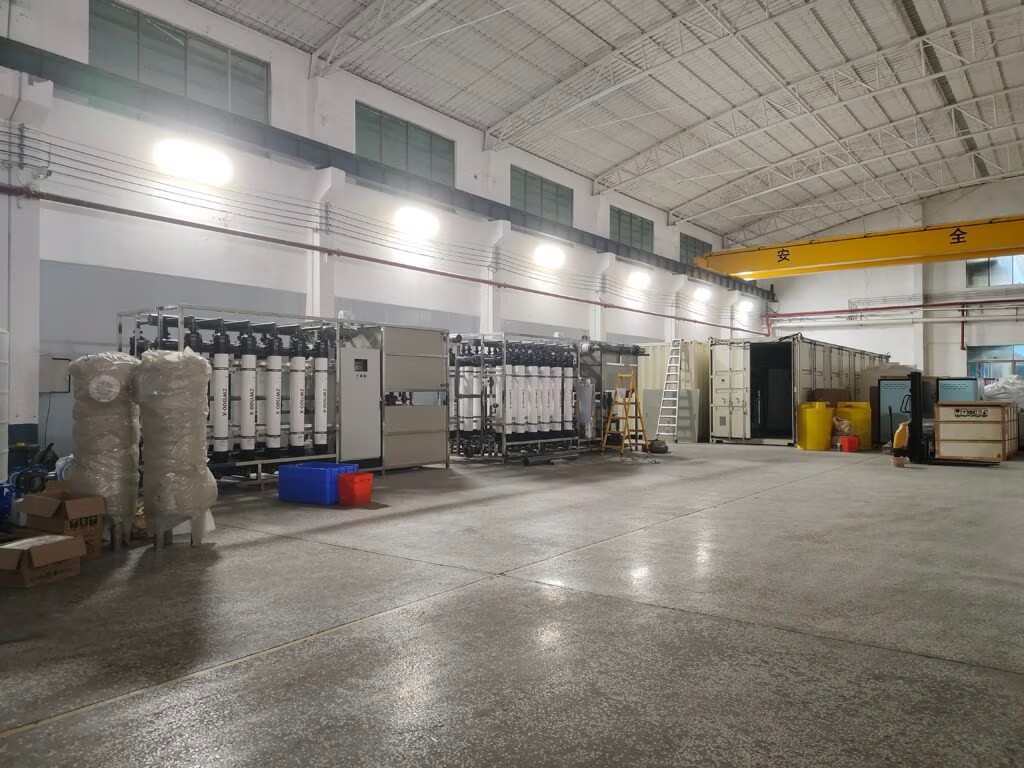
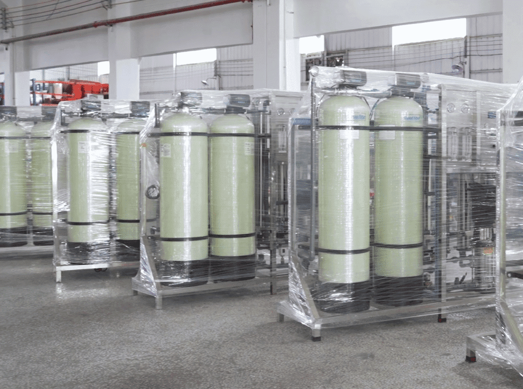
Ultrafiltration systems employ a modular and integrated design, with core components including a pretreatment unit, ultrafiltration membrane module, power unit, control unit, and cleaning unit. These modules work collaboratively to ensure stable, efficient, and long-term system operation.
Preprocessing unit
The purpose of pretreatment is to remove large particulate impurities, silt, fibers, etc., from the raw water to prevent them from scratching the membrane surface or clogging the membrane pores, thus reducing the risk of membrane fouling. Common pretreatment equipment includes:
- Raw water tank: Stores raw water, buffers water quality fluctuations, and ensures stable water supply.
- Bar screen: Removes large suspended solids, fibers, etc.
- Multi-media filter (quartz sand + activated carbon): Removes silt, rust, residual chlorine, and some organic matter.
- Precision filter: Intercepts fine particles and protects the ultrafiltration membrane.
Ultrafiltration membrane module
Ultrafiltration membranes determine the separation effect and water production efficiency. In industrial applications, hollow fiber membranes are generally used, with a single membrane module containing thousands of hollow fibers and the tube wall covered with micropores of 0.01–0.1 μm.
- Material Selection: Commonly used materials include polysulfone (PS), polyethersulfone (PES), and polyvinylidene fluoride (PVDF). Among them, PVDF has strong chemical stability, acid and alkali resistance, fouling resistance, and high mechanical strength, making it the mainstream choice for industrial water treatment.
- Structural Advantages: Hollow fiber membranes have a large specific surface area. A single 8-inch membrane module can have a membrane area of 35–65 m², significantly saving equipment space and improving water production efficiency.
- Module Types: Divided into internal pressure type (water flows from the inside of the fiber to the outside, impurities are trapped on the inner wall) and external pressure type (water flows from the outside of the fiber to the inside, impurities are trapped on the outer wall). The external pressure type has stronger anti-fouling capabilities and is suitable for high turbidity and highly polluted water quality.
Booster pump
The function of the booster pump is to pressurize the raw water to 0.1–0.5 MPa, providing sufficient driving force for ultrafiltration membrane separation. The pump’s flow rate and pressure need to be precisely matched according to the number of membrane modules, permeate flow rate, and water quality to ensure that the system operates at the optimal pressure, avoiding membrane damage due to excessive pressure or insufficient permeate production due to insufficient pressure.
Control Unit
Ultrafiltration systems can be equipped with PLC automation control, including a touchscreen, pressure sensors, flow sensors, and level sensors, to achieve fully automatic operation, real-time monitoring, fault alarms, and data logging. Key monitoring parameters include: inlet water pressure, product water pressure, concentrate pressure, product water flow rate, concentrate flow rate, and water temperature.

Cleaning unit
Membrane fouling is a core challenge in the operation of ultrafiltration systems. Colloidal substances, organic matter, and microorganisms in the raw water accumulate on the membrane surface, leading to decreased membrane flux, increased transmembrane pressure differential, and deterioration of product water quality. The cleaning unit offers three modes: online backwashing, online chemical cleaning, and offline chemical cleaning.
- Online backwashing: During normal system operation, backwashing occurs automatically every 15–60 minutes, using permeate water to flush the membrane surface, removing loosely accumulated impurities and restoring membrane flux.
- Online chemical cleaning: When the transmembrane pressure difference rises to a set value (typically >0.2 MPa), cleaning agents (such as sodium hypochlorite, hydrochloric acid, and sodium hydroxide) are automatically added to circulate and clean the membrane modules, removing stubborn contaminants.
- Offline chemical cleaning: In cases of severe membrane fouling, the membrane modules are removed and immersed in a cleaning tank for thorough cleaning, completely restoring membrane performance.
3. Performance parameters of ultrafiltration systems
The core parameters for evaluating the operating efficiency and performance of ultrafiltration systems include membrane flux, recovery rate, transmembrane pressure difference, water temperature, and cleaning cycle. These parameters directly determine the system’s water production capacity, energy consumption, membrane life, and operation and maintenance costs.
Membrane flux (J)
Membrane flux refers to the amount of water produced per unit membrane area per unit time, expressed in L/m²・h (LMH), reflecting the water production capacity of the membrane.
- Calculation formula: J = Permeate flow rate ÷ Total membrane area.
- Typical range: Industrial ultrafiltration membrane flux is typically 20–60 LMH, affected by water temperature, water quality, membrane material, and operating pressure.
- Water temperature influence: For every 1°C increase in influent water temperature, membrane flux increases by approximately 2–3%. Therefore, in winter, it is necessary to appropriately increase the operating pressure or adopt insulation measures.
Recovery rate
Recovery rate refers to the percentage of produced water flow to influent flow, reflecting the efficiency of water resource utilization.
- Calculation formula: Recovery rate = (Permeate flow rate ÷ Feed flow rate) × 100%.
- Typical range: In cross-flow filtration mode, the recovery rate of industrial ultrafiltration systems is typically 70–90%, with the remaining 10–30% being concentrate.
- Optimization objective: To maximize the recovery rate and minimize concentrate discharge while ensuring controllable membrane fouling.
Transmembrane pressure difference (TMP)
Transmembrane pressure difference refers to the difference between the feed water pressure and the product water pressure, measured in MPa, and is a core indicator reflecting the degree of membrane fouling.
Calculation formula: TMP = Inlet water pressure – Product water pressure.
- Normal range: During initial system operation, TMP is typically 0.05–0.1 MPa.
- Fouling assessment: When TMP rises to 0.2–0.3 MPa, it indicates severe membrane fouling, requiring immediate initiation of chemical cleaning.
Cleaning cycle
The cleaning cycle refers to the operating time between two cleaning cycles, reflecting the membrane’s antifouling ability and the quality of the water.
- Backwashing cycle: Typically 15–60 minutes, adjusted according to water turbidity, higher turbidity requires a shorter backwashing cycle.
- Chemical cleaning cycle: Under normal water quality, typically 1–3 months. Under highly polluted water quality, shortened to 2–4 weeks.
Summarize
With the continuous advancement of membrane material technology, ultrafiltration technology will develop towards higher flux, greater resistance to fouling, longer lifespan, greater intelligence, and lower energy consumption, providing more efficient and environmentally friendly solutions for global water treatment and fluid separation. If you still have questions about the working principles of ultrafiltration systems, please feel free to contact us for answers.